Hi Chris
I can't help by telling you about mine, as I had it replaced with a larger capacity unit. Somebody else did the work, so I don't know what (if anything) might have been changed.
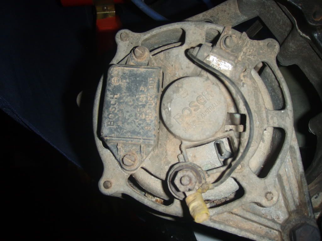
It looks like a fairly simple setup, with (I think) "internal" regulator (the black block on the left), main wire to the battery (formerly from the yellow connector on the stud - that's the alternator output) so I would guess the remaining wire is for the charge light on the dash.
The other device attached to the stud would be a noise suppression capacitor - leave it in place.
So.
Heavy wire (6mm^2 or more) from the stud to your battery - take care to protect this wire from shorting to earth.
"Normal" wire from the spade connector through the ignition switch (presuming you have one

), then through a 2 watt globe to earth/chassis/-ve - whatever you choose to call it. This wire is used to provide an initial excitation current for the field coil, and shouldn't be big - hence, this is one of those circumstances where "bigger is better" doesn't necessarily apply - 2W max is advised, and you may find the system will work without it.
I had a quick look at a GN schematic - that's essentially all it had, so I can't imagine your donor vehicle would've been more complicated.
Good luck.